Multipath Transit Time Open Channel Flow Meter
ALSONIC-AVM
Measure flow in open channels and partially filled pipes without any weirs or flumes required. SmartMeasurement’s meters are built for accuracy and regulatory compliance with long-term durability in real-world conditions.
Trusted in municipal water, wastewater, and environmental monitoring worldwide.
Size Range: (Std) 6″ – 1200″
Temperature Range: -22~+302 °F
Accuracy: 1 – 3% of reading
ALSONIC-AVM Multipath Transit-Time Open Channel Flow Meter
Accurate Flow Measurement Across the Water Column
The ALSONIC-AVM is a multipath ultrasonic transit-time flow measurement system designed for accurate flow measurement in rivers, canals, aqueducts, irrigation channels, wastewater channels and other open-channel applications.
Unlike non-contact radar velocity meters that measure velocity at the water surface, the ALSONIC-AVM measures velocity acoustically through the flowing water.
Multiple ultrasonic measurement paths can be installed at different elevations across the channel. Each acoustic path measures an average velocity along that path, providing a more representative measurement of the channel’s velocity distribution.
This makes the ALSONIC-AVM particularly well suited for large channels and applications where surface velocity may not accurately represent the average velocity of the entire flow cross-section.
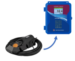
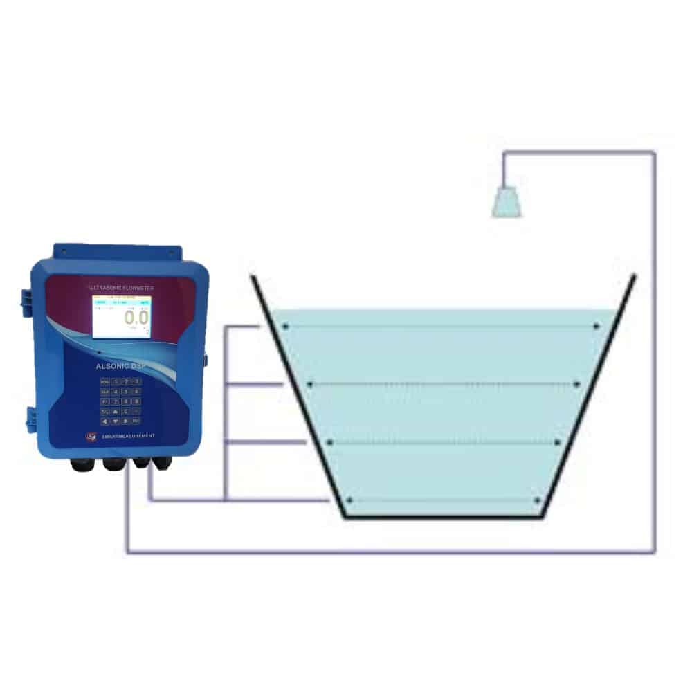
ALSONIC-AVM Measuring Principle
The ALSONIC-AVM uses the proven Area-Velocity method:
Q = A × V
where:
Q = Volumetric flow rate
A = Cross-sectional area of the flowing water
V = Representative average flow velocity
Water level is continuously measured and combined with the programmed channel geometry to determine the instantaneous wetted cross-sectional area.
Flow velocity is measured using pairs of ultrasonic transit-time transducers mounted on opposing sides of the channel.
The transducers transmit ultrasonic signals both upstream and downstream across the flowing water.
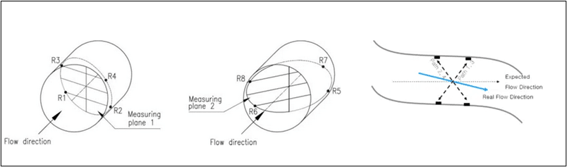
Because the flowing water affects the transit time of the ultrasonic signals, the difference between the upstream and downstream transit times is used to determine the average water velocity along each acoustic measurement path.
The flow computer combines the velocity measurements from the available submerged paths with the calculated cross-sectional area to determine total volumetric flow.
How Our Area Velocity Open Channel Technology Works
SmartMeasurement’s ALSONIC-AVM uses advanced area velocity technology to deliver precise open channel flow measurement. By combining ultrasonic transit-time sensors with a user-supplied level transmitter, the system calculates flow rate using the formula Q = v × A—where velocity (v) is measured across multiple paths and area (A) is determined from the liquid depth and channel width. As water levels change, up to four sensor pairs activate for consistent, high-accuracy readings in both partially filled pipes and open channels.
Why Choose SmartMeasurement’s Area Velocity Flow Meters?
Simplify Your Open‑Channel Flow Measurement
Avoid costly civil works such as flumes & weirs. Quick to deploy.
Get Reliable Results in Harsh Conditions
Effective measurements even in aerated, sediment-laden, or irregular flows.
Cut Upkeep & Lifecycle Costs
No moving parts with durable, low-maintenance instrumentation & minimal service requirements.
Easily Meet Regulatory Needs
Data recordkeeping, compliance-ready output formats for regulatory-grade logging and diagnostics.
Ready to Find the Right Flow Meter for Your Application?
The Right Solution for Engineers, Operators, and Environmental Professionals
Process & Environmental Engineers
- High-Accuracy Area × Velocity Measurement for precise flow data
- Minimal Installation Footprint for easy deployment
- SCADA & Data Logger Integration for seamless monitoring
- Ideal for Influent/Effluent, CSO, and Stormwater Studies
Plant, Operations, and Utility Managers
- IP68-Rated Transducers for harsh environments
- No Moving Parts = low maintenance
- Remote Diagnostics via Modbus/RS485
- 24/7 Durability for continuous operation
Compliance & Regulatory Officers
- Meets EPA Standards and regulatory monitoring requirements
- Tamper-Proof Audit Trails for reporting integrity
- Supports CSO, NPDES, and MS4 monitoring
- Permit Tracking for outfall and effluent compliance
Irrigation & Farm Managers
- Simple Installation with no complicated channel prep
- Remote Monitoring with minimal maintenance
- Water Rights & Cost Allocation support
- Seasonal & Permanent irrigation channel compatibility
Key Features of Our Open Channel Flow Meters
- No‑weir/no‑flume design — minimizes infrastructure cost and complexity.
- Integrated ultrasonic velocity + level sensors — (based on user’s preference): accurate flow in irregular/partially full channels.
- Data logging & diagnostics compliance-friendly – includes built-in loggers, USB export, diagnostic readouts, and Modbus.
- Rugged, low‑maintenance design – withstands fouling, solids, bubbles; IP66/NEMA4X rated.
- Wide flow & channel versatility – compatible with pipes, rectangular, trapezoidal, custom channels; supports erosion-prone and mixed flows.
- Advanced transit time transducers – able to measure very clean liquids as well as dirty liquids of up to 30% particles or bubbles.
- Ability to incorporate any Level Transmitter technology – users can choose any level technologies best suited for their application and connect the analog output to the SAVM flow computer for optimum Area Velocity Measurements.
- Versatility – users can choose from 2-4 pairs of transducers for conduits of greater than 1.5 meters and up to 30 meters of various shapes.
Technical Specifications
|
Measuring Principle: Anti-Round Beam, Transit-Time, Cross Correlation, Fast Fourier Transform |
| Measuring Width: ~30m |
| Accuracy: ±2.0% |
| Sensitivity: ±0.03 m/s |
| Analog I/O: Two 4~20mADC (Input) / Two 4~20mADC (Output) |
| Data Logger: 8 Mbytes |
| Display: Graphic Color LCD: Flow, Total, Velocity, Delta T, Ultrasonic Signal Shape, Frequency |
|
Relays: Two: • RS-232C • RS-485 |
|
Temperature: • Electronics: -20 ~ +60 °C • Transducers: -40 ~ +120 °C |
| Power: AC 110~220V or DC 12~24V |
| Enclosure: NEMA 4 (IP65) |
| Transducer: NEMA 7 (IP68, Waterproof) |
Set-Up Installation & Maintenance
Installation Guidelines
Installing SmartMeasurement’s area velocity flow meters must follow the example below. Our submersible velocity and non-submersible level sensors mount directly onto the channel bed or wall using standard brackets, while the remote open channel flow computer allows for fast, menu-driven configuration right from the field.
Calibration & Accuracy
SmartMeasurement’s Alsonic AVMs are factory-velocity calibrated and field-ready with intuitive, menu-driven calibration tools that simplify setup, removing the need to alter your channel. Advanced flow profiling software helps fine-tune accuracy in real-world conditions by adjusting to changes in water level, velocity, or debris. This ensures reliable and high-precision flow measurement across a variety of open-channel environments without sacrificing ease of use or installation speed.
Need help with installation?
Installation Procedure (Open Channel - Dual Path)
The open channel system may be used in rectangular, circular, trapezoid, or other shaped channels. Since the transducers create almost no restriction, virtually no head loss is created. The advanced DSP-based flow computer with cross-correlation and FFT technology allows this system to work in the most difficult applications, including those involving liquids with high concentrations of suspended solids & air or a large noise component. Please read this manual carefully before installation.
Step 1: Installing the Mounting Brackets
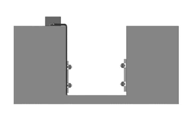
Selecting the right mounting place is the most important for ensuring accuracy. Please follow below steps to install the mounting bracket.
1) Install mounting brackets on the A side wall tightly. Considering highest and lowest water level, select distance between paths or distance between lower path and the bottom.
2) Confirm the installation place for the opposite side wall, then install brackets on the wall tightly.
Step 2: Assembling of Sensor and Bracket
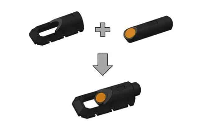
Insert sensors into brackets tightly.
Step 3: Adjusting of Sensor Direction
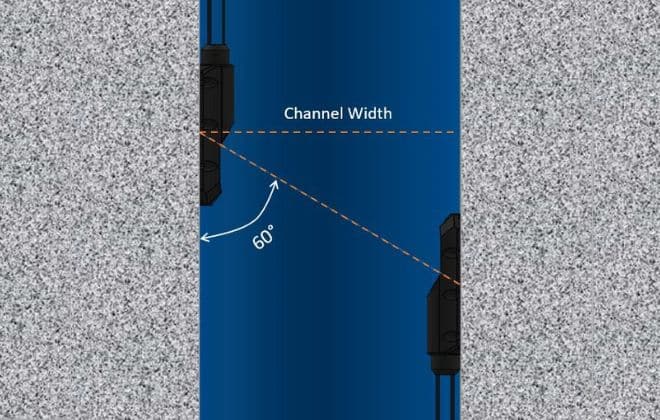
The Open Channel transducer angle is fixed to 60°. The angle is measured from the CENTER of the sensor to the mounting wall.
In order to receive a good signal for best accuracy, all transducers must face diagonally.
For trapezoidal or circular channels, rotate the sensors on both walls so that they face each other.
Step 4: Install Flowmeter and Connect
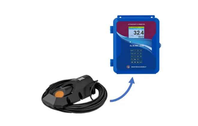
Cables are integrated with transducers, so connect the other side of cable to the flow computer.
Step 5: Connect the Remaining Cables
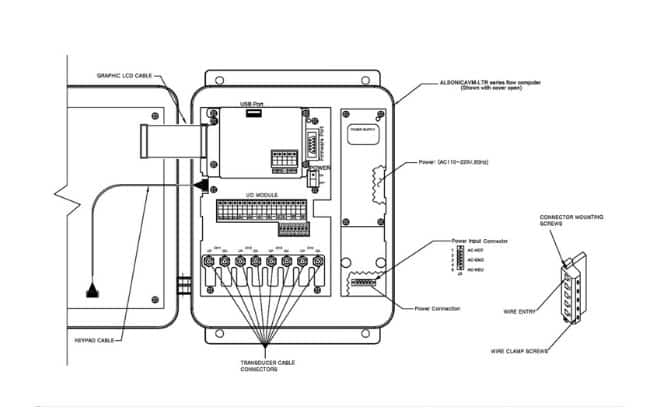
Go to installation manual and connect all the necessary cables to the flow computer
Why Multipath Velocity Measurement Matters
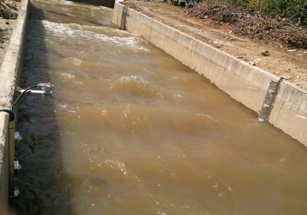
Velocity in an open channel is rarely uniform.
Water near the channel walls and bottom normally travels more slowly because of friction, while velocities in other portions of the channel can be significantly higher.
Flow conditions can become even more complex because of:
- Turbulence
- Changing water levels
- Irregular channel geometry
- Upstream or downstream obstructions
- Upstream or downstream obstructions
- Hydraulic disturbances
- Non-uniform velocity profiles
A single velocity measurement may therefore not adequately represent the entire flow cross-section.
The ALSONIC-AVM can utilize multiple acoustic measurement paths installed at different elevations, providing substantially more information about the actual velocity distribution within the flowing water.
As water level changes, the flow computer utilizes the available submerged acoustic paths when determining representative channel velocity and total flow.
ALSONIC-AVM vs. Surface-Velocity Radar
Non-contact radar velocity meters offer important advantages in applications where installing sensors in the water is difficult or undesirable.
However, radar velocity instruments measure the movement of the water surface.
To calculate total flow, the measured surface velocity must be related to the average velocity of the complete water cross-section. The accuracy of this relationship depends on the hydraulic conditions and site-specific velocity distribution.
In applications with highly turbulent or irregular surface conditions, surface velocity may not always be representative of the average velocity throughout the water column.
The ALSONIC-AVM takes a different approach.
Instead of measuring only surface movement, ultrasonic transit-time measurement paths pass through the flowing water, providing direct measurements of average velocity along each acoustic path.
Multiple measurement elevations can therefore provide a more representative assessment of the channel’s velocity distribution.
Surface Radar
Measures: Surface velocity
Advantages:
- Completely non-contact
- Simple installation
- No sensor exposed to water or debris
- Excellent for suitable rivers and channels with representative surface conditions
Considerations:
- Measures surface movement rather than velocity within the water column
- Requires a relationship between surface velocity and mean channel velocity
- Highly disturbed or turbulent surfaces can complicate the relationship between measured surface velocity and total channel flow
ALSONIC-AVM Multipath Transit-Time
Measures: Average water velocity across submerged acoustic paths
Advantages:
- Direct velocity measurement through the flowing water
- Multiple measurement elevations available
- Better representation of non-uniform velocity distributions
- Particularly suitable for large channels
- Well suited for applications where surface conditions do not adequately represent the overall flow
Multipath Measurement
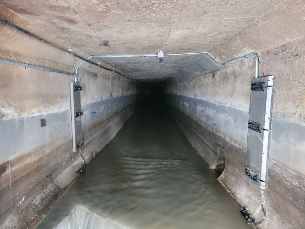
The ALSONIC-AVM can be configured with up to four ultrasonic measurement paths.
Each path consists of ultrasonic transducers installed on opposing sides of the channel. The acoustic beam crosses the flowing water diagonally, allowing the instrument to determine average velocity along the measurement path.
Installing paths at multiple elevations allows the system to characterize velocity at different portions of the water column.
When water level changes, only properly submerged and operational measurement paths are used by the flow computer.
This multipath approach can provide a significantly more representative velocity measurement than relying on a single velocity measurement location.
Advanced Ultrasonic Signal Processing
Open-channel applications can contain suspended solids, entrained air and significant acoustic noise.
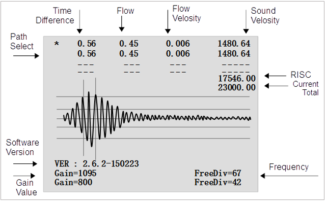
The ALSONIC-AVM uses advanced digital signal processing, including cross-correlation and FFT techniques, to identify and process ultrasonic signals under difficult measurement conditions.
This signal-processing capability helps maintain reliable transit-time measurements in demanding industrial, wastewater and natural-water applications.
Specific performance in applications containing high concentrations of suspended solids or entrained gas should be evaluated based on actual operating conditions.
How Our Area Velocity Open Channel Technology Works
SmartMeasurement’s ALSONIC-AVM uses advanced area velocity technology to deliver precise open channel flow measurement. By combining ultrasonic transit-time sensors with a user-supplied level transmitter, the system calculates flow rate using the formula Q = v × A—where velocity (v) is measured across multiple paths and area (A) is determined from the liquid depth and channel width. As water levels change, up to four sensor pairs activate for consistent, high-accuracy readings in both partially filled pipes and open channels.

Why Multipath Velocity Measurement Matters
Velocity in an open channel is rarely uniform.
Water near the channel walls and bottom normally travels more slowly because of friction, while velocities in other portions of the channel can be significantly higher.
Flow conditions can become even more complex because of:
- Turbulence
- Changing water levels
- Irregular channel geometry
- Upstream or downstream obstructions
- Bends and transitions
- Hydraulic disturbances
- Non-uniform velocity profiles
A single velocity measurement may therefore not adequately represent the entire flow cross-section.
The ALSONIC-AVM can utilize multiple acoustic measurement paths installed at different elevations, providing substantially more information about the actual velocity distribution within the flowing water.
As water level changes, the flow computer utilizes the available submerged acoustic paths when determining representative channel velocity and total flow.
ALSONIC-AVM vs. Surface-Velocity Radar
Non-contact radar velocity meters offer important advantages in applications where installing sensors in the water is difficult or undesirable.
However, radar velocity instruments measure the movement of the water surface.
To calculate total flow, the measured surface velocity must be related to the average velocity of the complete water cross-section. The accuracy of this relationship depends on the hydraulic conditions and site-specific velocity distribution.
In applications with highly turbulent or irregular surface conditions, surface velocity may not always be representative of the average velocity throughout the water column.
The ALSONIC-AVM takes a different approach.
Instead of measuring only surface movement, ultrasonic transit-time measurement paths pass through the flowing water, providing direct measurements of average velocity along each acoustic path.
Multiple measurement elevations can therefore provide a more representative assessment of the channel’s velocity distribution.
Surface Radar
Measures: Surface velocity
Advantages:
- Completely non-contact
- Simple installation
- No sensor exposed to water or debris
- Excellent for suitable rivers and channels with representative surface conditions
Considerations:
- Measures surface movement rather than velocity within the water column
- Requires a relationship between surface velocity and mean channel velocity
- Highly disturbed or turbulent surfaces can complicate the relationship between measured surface velocity and total channel flow
ALSONIC-AVM Multipath Transit-Time
Measures: Average water velocity across submerged acoustic paths
Advantages:
- Direct velocity measurement through the flowing water
- Multiple measurement elevations available
- Better representation of non-uniform velocity distributions
- Particularly suitable for large channels
- Well suited for applications where surface conditions do not adequately represent the overall flow
Multipath Measurement
The ALSONIC-AVM can be configured with up to four ultrasonic measurement paths.
Each path consists of ultrasonic transducers installed on opposing sides of the channel. The acoustic beam crosses the flowing water diagonally, allowing the instrument to determine average velocity along the measurement path.
Installing paths at multiple elevations allows the system to characterize velocity at different portions of the water column.
When water level changes, only properly submerged and operational measurement paths are used by the flow computer.
This multipath approach can provide a significantly more representative velocity measurement than relying on a single velocity measurement location.
Advanced Ultrasonic Signal Processing
Open-channel applications can contain suspended solids, entrained air and significant acoustic noise.
The ALSONIC-AVM uses advanced digital signal processing, including cross-correlation and FFT techniques, to identify and process ultrasonic signals under difficult measurement conditions.
This signal-processing capability helps maintain reliable transit-time measurements in demanding industrial, wastewater and natural-water applications.
Specific performance in applications containing high concentrations of suspended solids or entrained gas should be evaluated based on actual operating conditions.
Area Velocity Open Channel Flow Meter Applications
Municipal Water & Wastewater
From monitoring influent and effluent flows to keeping tabs on CSO events, SmartMeasurement’s area velocity flow meters are built to handle the challenges of municipal water systems. Once the correct installation procedure is followed above, , they provide the accurate data needed to meet regulatory standards and keep treatment operations running smoothly.
Stormwater & Environmental Monitoring
For runoff studies, stream and river gauging, or NPDES permit compliance, SmartMeasurement’s ultrasonic open-channel meters offer the accuracy and durability needed in variable flow environments. These meters withstand harsh conditions with its submersible design and lack of moving parts. Ideal for long-term deployments in environmental monitoring stations and urban stormwater systems.
Agricultural & Irrigation
In agriculture, every drop counts. SmartMeasurement’s area velocity flow meters give irrigation districts, growers, and water managers the tools to accurately track flow in open ditches, canals, and furrows. Our open channel flow meters provide dependable data, even in low-velocity or partially filled channels, so you can monitor distribution, reduce waste, and meet irrigation efficiency standards.
Industrial Process & Mining
Industrial and mining sites rely on robust solutions to monitor and ultimately manage water flow in cooling systems, discharge channels, and heap leach operations. SmartMeasurement's ultrasonic area velocity meters can handle both variable flow situations and debris-laden water, providing plant engineers and environmental teams with dependable data for process optimization and regulatory reporting.
Area Velocity Open Channel Flow Meters the Alsonic AVM FAQs
How accurate are SmartMeasurement’s area velocity meters, especially in low-flow or reverse-flow scenarios?
The ALSONIC‑AVM ultrasonic meter delivers ±2-5% accuracy in challenging conditions like low‑flow, surcharged, or aerated channels, thanks to its multi-path transit-time sensing system. With velocity profiling it can reach to +/- 1%.
Are your area velocity meters capable of continuous, real-time use in heavy-duty environments?
Yes, the model is rated for rugged field environments with IP67/IP68 protection for sensors and mounting enclosures. They offer integrated diagnostics, fast response (< 1 s), and robust velocity and level profiling.
Is installation easy in confined or fixed channels without pre-installed devices?
Absolutely. The sensors are non-restrictive (no flume/weir required), mount easily via spring bands or brackets, and fit a range of geometries. It also includes optional laser alignment tools, graphic LCDs, and DSP-driven setup with menu‑guided channel profiles.
Are sensors rated for immersion and harsh environments?
Yes—sensors and enclosures offer IP67/IP68 protection, stainless mounting hardware, and operation across –20 °C to +60 °C. The meter supports channel widths from 150 mm to 30 m+ and handle up to 30% suspended solids.
Can your area velocity meters handle channels with debris, sediment, or irregular shapes?
Yes. The Alsonic AVM uses up to four ultrasonic transducers that self-select based on submersion, enabling accurate profiling even in debris-laden or irregular channels.
Do the area velocity meters support industry-standard protocols and telemetry?
Yes. This model is compatible with PLCs, SCADA systems, and user-supplied level sensors to calculate flow via Level × Velocity logic. Standard outputs include 2×4–20 mA and pulse relays; optional RS‑485 with Modbus/SDI‑12; plus remote display panels and dataloggers.
How simple is field calibration and alignment?
The Alsonic AVM model uses transit-time DSP and cross-correlation to automatically adjust to changing water profiles.
Is fouling or maintenance a concern?
The Alsonic AVM sensors resist clogging, and up to 4 path profiling accommodates different flow velocities at each depth on the channel. Our built-in diagnostics, oscilloscope readouts, and easy access to mounting hardware further simplify upkeep.
Let’s Get Your System Flowing
Get expert advice, fast quotes, and reliable equipment.
